
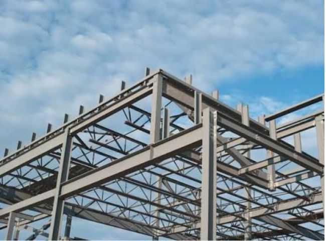
Steel Shop Drawings Australia – Precision Structural Steel Detailing Services
Matrix Steel Solutions delivers accurate, code-compliant steel shop drawings Australia-wide, giving fabricators, erectors, and steel detailing companies the fabrication-ready documentation they need to cut, punch, weld, bolt, and erect structural steel with zero guesswork. Every drawing package we produce is built in Tekla Structures and checked against AS 4100, AS/NZS 5131, AS/NZS 1170.2, and the National Construction Code (NCC), so your fabrication shop and site crew are working from a single, coordinated set of documents from day one.
Whether you need shop drawings for a single-storey industrial shed in regional Victoria, a multi-level commercial tower in Sydney, or a resources-sector platform in Western Australia, our detailing team produces piece-by-piece fabrication drawings, erection drawings, and connection details that match your project's engineering intent exactly, with no clashes, no missing dimensions, and no costly re-work on the shop floor.
What Are Steel Shop Drawings?
Steel shop drawings are the fabrication-level documents that translate a structural engineer's design drawings into instructions a fabricator can actually cut and weld from. Where an engineer's general arrangement drawing shows member sizes, load paths, and overall geometry, a shop drawing goes several steps further: it specifies exact member lengths, cope and mitre cuts, bolt hole patterns and spacing, weld symbols and weld sizes, plate thicknesses, camber, and every piece mark that will appear stencilled on the steel itself.
In practical terms, a complete shop drawing package includes:
- Fabrication (piece) drawings for every individual beam, column, brace, plate, and cleat, each carrying a unique piece mark
- Assembly and erection drawings showing how pieces come together on site, referenced to grid lines and elevations
- Connection design drawings detailing bolted and welded connections, including bolt grade, bolt diameter, and hole tolerances
- Anchor bolt setting plans for the foundation contractor, issued early so bolts can be cast before steel arrives
- Bill of materials and cutting lists that feed directly into the fabricator's CNC and plasma-cutting equipment
- Purlin, girt, and bracing layout drawings for roof and wall framing systems
- Staircase, handrail, and miscellaneous steel detailing where applicable
Because Australian fabricators increasingly run CNC-driven workshops, our shop drawings are structured so that dimensional and hole information can be extracted straight into DSTV/NC1 files for automated processing, cutting the time between drawing issue and steel cutting.
Why Accurate Shop Drawings Matter for Australian Construction Projects
A steel-framed building is only as good as the drawings that guide its fabrication. When shop drawings are inaccurate, incomplete, or fail to reflect the latest engineering revision, the consequences show up on site: bolts that don't line up, members that arrive short, connections that need field modification, and erection crews standing idle while a fix is worked out. On a commercial or industrial project, every hour of downtime translates directly into cost.
Australia's construction environment adds specific pressures that make precision detailing non-negotiable. Wind and cyclone loading under AS/NZS 1170.2 varies dramatically between a Melbourne warehouse and a North Queensland structure in a cyclonic wind region, and that difference has to be carried through correctly into connection capacities and anchor bolt sizing. Corrosion protection requirements differ between a coastal project in Perth and an inland site in the NSW Riverina, which affects surface treatment notes on the drawings. Seismic detailing provisions under AS 1170.4 apply differently depending on the site's hazard factor. Getting these variables wrong at the shop drawing stage doesn't just cause delay — it can mean steel that doesn't satisfy the structural engineer's certification, which is a serious compliance problem under the NCC.
There is also the reality of long supply chains. Steel fabricated in one state and erected in another, or steel ordered against long lead times from mills, means there is little room to "fix it on site." Shop drawings have to be right the first time, because by the time steel reaches site, the opportunity to cheaply correct an error has usually passed.
Compliance with Australian Standards: AS 4100, AS/NZS 5131, AS/NZS 1170.2, and the NCC
Every shop drawing package we issue for Australian projects is developed with direct reference to the governing standards:
AS 4100 (Steel Structures) sets out the design and detailing requirements for steel structures in Australia, including member capacity, connection design principles, and fabrication tolerances. Our detailers cross-check member sizes, hole clearances, and edge distances against AS 4100 provisions so that what appears on the shop drawing is buildable within the tolerances the standard allows.
AS/NZS 5131 (Structural Steelwork — Fabrication and Erection) is the standard fabricators and detailers increasingly work to directly, since it sets Construction Categories (CC1 to CC4) that determine the level of documentation, weld inspection, and traceability required for a given structure. We identify the applicable Construction Category early in a project and tailor drawing notes, weld procedure references, and inspection call-outs accordingly, so fabricators aren't left guessing what level of quality documentation the job demands.
AS/NZS 1170.2 (Wind Actions) governs the wind loads that connection design and anchor bolt sizing must resist. Because our drawings are developed in coordination with the project engineer's load information, wind region and terrain category assumptions are reflected consistently across every connection detail and base plate.
The National Construction Code (NCC) sits above these standards as the overarching regulatory framework, and our documentation is structured to support the certification and building approval process — clear revision control, drawing registers, and issue-for-construction stamps that a certifier or building surveyor can follow without ambiguity.
Our Steel Shop Drawing Services in Australia
Fabrication Drawings
Every individual steel member — beams, columns, braces, cleats, gusset plates, base plates, and stiffeners — is drawn to a level of detail a fabricator can work from without needing to refer back to the design drawings. Each piece carries a unique piece mark, exact cut length, cope and notch details, hole locations and diameters, and weld preparation notes.
Erection Drawings
Erection drawings show how the individually fabricated pieces come together into the completed structure. They are referenced to the project's grid lines, levels, and elevations, and are colour-coded or sequenced where useful so the erection crew can plan lift sequences and temporary bracing requirements before steel arrives on site.
Connection Design and Detailing
Bolted and welded connections are detailed to match the connection design basis provided by the structural engineer, whether that's simple shear connections, moment connections, or braced-frame connections. Bolt grade (8.8/S or 10.9/S), bolt diameter, hole type (standard, oversize, or slotted), and weld size and type are all called out explicitly.
Anchor Bolt Setting Plans
Because foundations are typically poured well before steel arrives, anchor bolt plans are issued early in the drawing sequence. These plans give the civil/foundation contractor exact bolt locations, projections, and orientation relative to grid lines, reducing the risk of a bolt cage being set incorrectly and steel arriving to a foundation it can't be bolted to.
Purlin, Girt, and Bracing Layouts
For portal-frame sheds, warehouses, and industrial buildings — a very common structure type across Australian regional and metro industrial precincts — we detail purlin and girt layouts, lapping arrangements, bridging, and bracing to match the cladding and wind-load requirements of the project.
Bill of Materials and Cutting Lists
Every drawing package is accompanied by a bill of materials broken down by piece mark, profile, length, and weight, structured so it can be imported directly into a fabricator's ERP or nesting software for material ordering and cutting optimisation.
Software and Technology We Use
Our detailing team works primarily in Tekla Structures, building a full 3D model of the structure before any 2D shop drawing is extracted. Modelling in 3D first means every connection is checked for physical clashes — bolt heads against adjacent members, weld access, service penetrations — before a single drawing is issued, which is where the real value of BIM-based detailing shows up: problems get caught on screen, not on the erection site.
We also work in Advance Steel and SDS/2 where a client's existing project or fabricator preference calls for it, and we export DSTV/NC1 files for CNC-driven fabrication lines, IFC files for coordination with architects and services engineers, and PDF/DWG sets for review and approval workflows. Where a client uses a common data environment for a project, we can issue drawings and models directly into that environment to support the wider project team.
Scope of Steel Shop Drawings We Provide
Our shop drawing capability covers the full range of structural steel construction types found across the Australian market:
- Industrial sheds, warehouses, and portal-frame buildings
- Multi-storey commercial and residential steel-framed structures
- Mezzanine floors and platforms
- Mining and resources-sector structures, including conveyor gantries and equipment support steel
- Bridges and pedestrian structures
- Staircases, ladders, walkways, and handrails
- Miscellaneous and architectural steelwork, including feature stairs and balustrades
- Retrofit and strengthening steelwork for existing structures
Our Shop Drawing Process
We follow a structured sequence on every project to keep drawing issue predictable and coordinated with your fabrication schedule:
1. Model and Document Review — We start by reviewing the structural engineer's design drawings, specifications, and any architectural or services drawings that affect steel geometry, identifying long-lead items and connection types early.
2. 3D Modelling in Tekla Structures — The full structure is modelled in 3D, including every connection, so clashes and buildability issues are identified before drawings are issued.
3. Connection Design Coordination — Where connection design is being carried out by the structural engineer or a connection design engineer, we coordinate directly to make sure the modelled connections match the approved design basis.
4. Internal Quality Check — Every drawing package goes through an internal check against the 3D model, the structural drawings, and the applicable Australian Standards before it leaves our team.
5. Issue for Fabrication/Approval — Drawings are issued in the format your project needs — PDF, DWG, DSTV/NC1 — with clear revision numbering and a drawing register so everyone on the project is working from the current issue.
6. Revision Management — As RFIs are answered and design changes come through, we update the model and reissue only the affected drawings, with full revision tracking so fabricators always know exactly what changed.
Industries We Serve
We provide steel shop drawing services to structural steel fabricators, steel detailing companies, structural engineering firms, and construction companies across Australia, spanning industrial and warehouse construction, commercial and multi-storey building projects, mining and resources infrastructure, transport and bridge projects, and residential steel-framed developments. Our detailers are equally comfortable supporting a fabricator's in-house drawing office as an overflow resource, or acting as the sole detailing provider for a project from concept through to as-built documentation.
Our Detailing Team's Approach to Australian Projects
Detailing steel for the Australian market requires more than software proficiency — it requires familiarity with how Australian fabricators actually run their workshops, the tolerances their CNC lines expect, and the way local erection crews sequence a lift. Our detailers work to Australian units and conventions throughout, apply the correct bolt and weld symbols used in local practice, and structure drawing sheets in a layout Australian fabrication shops and site supervisors are already used to reading. Where a project involves interstate fabrication and erection — steel fabricated in one state and shipped for erection in another — we account for transport constraints on piece size and weight in how members are broken down for fabrication, so oversized or overweight pieces aren't discovered as a logistics problem after cutting has already started.
Benefits of Outsourcing Steel Shop Drawings to Matrix Steel Solutions
Cost Efficiency: Maintaining an in-house detailing team for peak workloads is expensive. Outsourcing gives fabricators access to a full detailing capability without the fixed overhead of employing and retaining detailers year-round.
Faster Turnaround: Because detailing is our core focus, drawing packages move through modelling, checking, and issue faster than they typically would competing for internal resources against other priorities.
Standards Compliance Built In: Every drawing is checked against AS 4100, AS/NZS 5131, and relevant wind and seismic loading standards, reducing the risk of non-compliant documentation reaching the fabrication shop.
Reduced Rework: 3D clash detection during modelling catches connection and geometry problems before steel is cut, avoiding the cost of remaking a fabricated piece that doesn't fit on site.
Scalability: Whether you need one detailer's worth of output for a small shed project or a full team across a multi-tower commercial development, our resourcing scales to match your project pipeline.
Quality Assurance and Review Process
Quality control is built into every stage of our workflow rather than treated as a final check. Our 3D-first modelling approach in Tekla Structures means clash detection happens continuously as the model is built, not as an afterthought. Before any drawing package is issued, it passes through an internal review against the structural engineer's design documentation, the applicable Australian Standards, and the project's connection design basis. Revision control is maintained through a drawing register that tracks every issue, its date, and the reason for change, so fabricators and site teams always have visibility of what is current and what has been superseded.
Turnaround Time and Project Management
We understand that shop drawings sit on the critical path for procurement, fabrication, and site programming. Our team works to agreed drawing issue schedules aligned with your project's fabrication and erection sequence, prioritising early-trade items like anchor bolt plans so foundation work isn't held up, and structuring the remaining drawing issue in the sequence your fabrication shop needs steel released. Where a project involves staged design development or ongoing RFIs, we manage revisions transparently so nobody on the project team is left working from an outdated drawing.
Why Choose Matrix Steel Solutions for Steel Shop Drawings in Australia
Matrix Steel Solutions combines Tekla Structures modelling expertise with a working knowledge of AS 4100, AS/NZS 5131, AS/NZS 1170.2, and NCC requirements, giving Australian fabricators and structural engineering firms a detailing partner that understands both the software and the regulatory framework the drawings need to satisfy. We produce fabrication-ready documentation that CNC and plasma-cutting equipment can work from directly, connection details that match the engineer's design basis without ambiguity, and a revision process that keeps every stakeholder — fabricator, erector, engineer, and certifier — working from the same current information.
Common Steel Shop Drawing Challenges We Solve
Detailing teams and fabricators run into the same handful of problems on almost every project, and our process is built specifically to head them off:
Late or Incomplete Connection Design: When connection design lags behind the fabrication schedule, drawings either get delayed or get issued with assumed connections that later have to be redone. We coordinate directly with the project's connection design engineer and sequence our modelling so generic member drawings can progress while connection-specific details are finalised, rather than stalling the whole package.
Mismatched Revisions Between Engineer and Detailer: A common source of site rework is a fabricator working from a shop drawing that predates the latest structural revision. Our drawing register cross-references every issue against the structural engineer's revision number, so it's immediately clear whether a shop drawing reflects the current design.
Construction Category Confusion Under AS/NZS 5131: Many fabrication teams are still adjusting to the documentation and inspection implications of Construction Categories CC1 through CC4. We flag the applicable category on the drawing package itself and tailor weld inspection and traceability notes accordingly, so there's no ambiguity about what level of quality documentation a structure requires.
Cyclonic and High-Wind Region Detailing: Structures detailed for a standard wind region but built in a cyclonic area (or vice versa, where drawings are over-specified for a low-wind site) waste time and money. We confirm wind region classification against AS/NZS 1170.2 early and make sure connection and anchor bolt capacities on the drawings match the actual site conditions.
Clashes Discovered During Erection: Physical clashes between steel and services, or between adjoining structural members, are far cheaper to resolve on screen than on site. Our 3D-first Tekla modelling catches these before drawings are issued rather than after steel has been cut.
What to Include When Requesting a Steel Shop Drawing Quote
To give you an accurate quote and realistic drawing schedule, it helps to provide the structural engineer's design drawings and specification, any architectural drawings that affect steel geometry (openings, cladding lines, façade fixings), the applicable wind region and any seismic hazard information, the connection design basis if it has already been developed, your preferred detailing software and file formats for handover, and your target fabrication and erection dates so we can sequence drawing issue to match your programme. The more of this information is available upfront, the faster we can move from model kickoff to issue-for-fabrication drawings.
Frequently Asked Questions
What is the difference between shop drawings and design drawings?
Design drawings, produced by the structural engineer, show overall geometry, member sizes, and load paths. Shop drawings translate that design intent into fabrication-level detail — exact cut lengths, bolt hole patterns, weld sizes, and piece marks — that a fabricator can actually cut and weld from.
Do you detail to AS/NZS 5131 Construction Categories?
Yes. We identify the applicable Construction Category (CC1–CC4) for each project and structure our drawing notes, weld inspection call-outs, and traceability documentation to match what that category requires.
Can you provide DSTV/NC1 files for CNC fabrication equipment?
Yes. Our Tekla Structures models can export DSTV/NC1 files directly, along with IFC for coordination and PDF/DWG sets for review and approval.
Do you work with fabricators outside the state where your team is based?
Yes. Our shop drawing service is delivered remotely and supports fabricators, detailing offices, and construction companies across all Australian states and territories, including projects in cyclonic wind regions and seismic hazard areas.
How quickly can anchor bolt plans be issued?
Anchor bolt plans are typically prioritised early in the drawing sequence, since foundation work usually can't proceed without them. Exact timing depends on how much of the structural design and connection basis is finalised at project start.
Can you detail structures for both metric and imperial equipment lines?
Yes. While Australian projects are documented in metric units throughout, we accommodate fabricators whose CNC and workshop equipment expects specific tolerance or unit conventions, confirming this during project setup so drawing output matches your shop floor without conversion errors.
If your fabrication shop, detailing office, or construction project needs accurate, standards-compliant steel shop drawings anywhere in Australia, get in touch with our team to discuss your project scope, timeline, and drawing format requirements.